If you are for looking a deep technical analysis of Yagi design and development then this review will disappoint you. This review is about my personal experiences with a G0KSC 6M8LFA in comparison to the much older (and currently much more widely used) M2 6M7JHV.
Just over a year ago I became aware of a number of new 6m antenna designs being created by Justin G0KSC. These designs, published on Justin's website (Ref 1) and elsewhere, seemed to offer very good overall performance combined with repeatability and ease of construction. In one of my many e-mails to Justin I mentioned the K5AND / W6JKV 6M DXers BBQ - one thing led to another and resulted in Justin making a presentation on his antenna designs at the BBQ in October last year whilst in the States setting up the deal with Force 12.
In my 32 years on 6m from various locations around the world, I have built, bought and tried many different antennas for 6m. These days, most commercial designs "do what they say on the tin" - but only that - watch out for what's not included on the tin;-).
 The 6M7JHV was originally designed
for Dave Batacho, N5JHV and has been around for over a decade. (See G3ZSS 1999
review - Ref 2). I replaced my M2 6M5X with a 6M7JHV in early 2002 and
have been using JHV antennas ever since. In 2002 I purchased a pair of 6M7JHVs
but the first came down before the second went up:-(
The 6M7JHV was originally designed
for Dave Batacho, N5JHV and has been around for over a decade. (See G3ZSS 1999
review - Ref 2). I replaced my M2 6M5X with a 6M7JHV in early 2002 and
have been using JHV antennas ever since. In 2002 I purchased a pair of 6M7JHVs
but the first came down before the second went up:-(
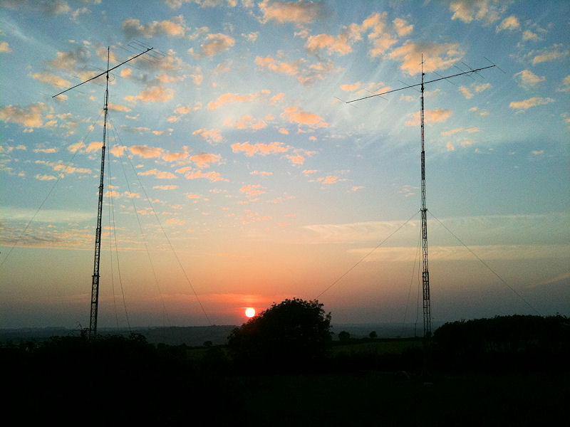
The 6M7JHV is just under 9.35 metres long and is a lightweight antenna. Early versions (mine) also suffered from mechanical element resonance in even low velocity winds - resulting in element failure and a field full of aluminium spikes. Current versions are much better in this respect and have mechanical dampers within the element mounting. Boom failure was also an issue but dual truss support lines help prevent this.
The T-match feed is sturdy and waterproof with direct N-type connector. The Allen screw shorting bar locks are certainly not suitable for frequent adjustment. Initially it can be tricky to obtain a decent SWR as it is affected by height and proximity to other hardware. However, once setup it gives a good match.
Correctly supported, braced and weatherproofed the 6M7JHV has proved to be stable, reliable and a very good all round antenna for weak signal and eme work. I have one in IO70, one in IL39 and one used for portable / expedition work.
The 6M8LFA
My version of the G0KSC 6M8LFA is an early model created by Justin. As per the construction details to be found on Justin's website it uses box section aluminium tube and home made Perspex boom to element mounts. One piece elements insulated from the boom differentiate this design.
This version of the 6M8LFA is somewhat longer than the 6M7JHV at 11.8m. The box section boom increases wind loading compared to tube but makes for much easier construction and assembly.
In my version mechanical resonance of both boom and elements at low wind speeds is a problem. Fortunately the sheep don't seem bothered by the noise.
The dual trussing and damping techniques techniques used on the 6M7JHV will no doubt resolve the above issues.
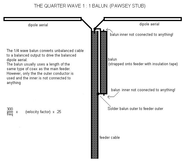
The Loop Feed is of course the unique design feature of the G0KSC Loop Fed Array series of antennas. The loop is designed to present a direct 50 Ohm balanced feed (unlike most "conventional" Yagis which tend to have a low impedance that requires matching to the coax). Each end of the loop has a trombone section of tubing for initial set up - the joints are then coated with conductive grease [Vine Antennas - Ref 3], clamped in place with hose clamps and thoroughly weatherproofed with self-amalgamating tape. (For the ultimate one piece loop these joints could be aluminium welded.)

LFA Loop and Choke Balun
To feed the LFA all that is required is a 50 Ohm Balun. Unfortunately Balun design issues have introduced some controversy and confusion into discussion of Justin's designs - particularly with regards to the correct design of a Pawsey Stub. There are many different types of Balun - purists would say that some of the designs are not even Baluns at all. But in reality it's not that difficult - surprisingly I found that in practice a choke "balun" created by winding 6 turns of Westflex103 was all that was required. Of course a correctly constructed coax sleeve "bazooka" balun as described by Peter PA2V in SN103 or a Pawsey stub (Fig 1) will in theory do a better job - but there are more connections to get wet and degrade over time;-). *G0KSC recommends the use of a true Balun rather than a choke.

Test rig
To enable adjustments I mounted the 8LFA on a tilt over lighting mast with the loop at shoulder height and the LFA pointing up at about 45degrees. I was amazed at how easy it was to obtain SWR 1:1 with R=50 and X=0 anywhere in the bottom half of 50MHz by simple adjustment of the loop "trombone". I was even more amazed to find that the SWR remained at 1:1 with R=50 and X=0 when I lifted the 8LFA to 10m and then 20m. [I was looking for the hidden dummy load:-)] The frequency at which R=50 and X=0 occurred did move up by about 50kHz but the SWR remained virtually flat below 1.1:1 for about 400kHz.
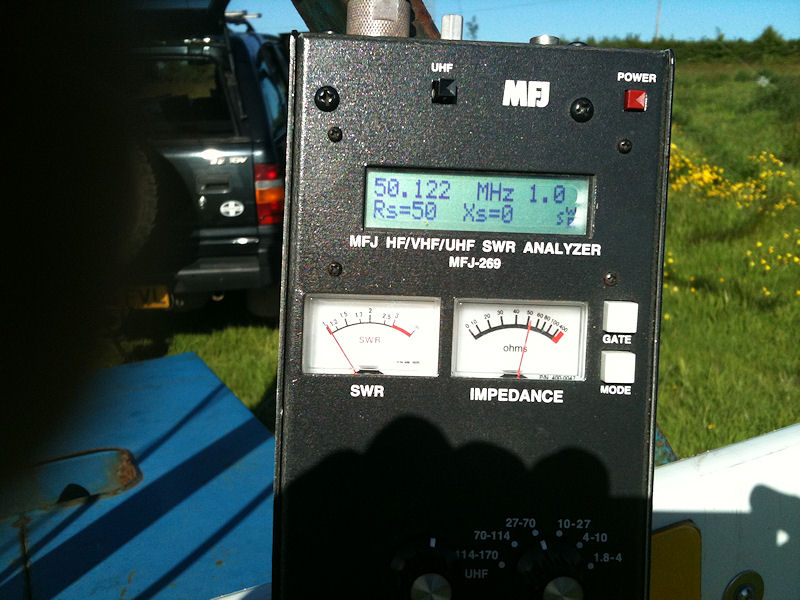
A decent match - Rs =50Ohm Xs = 0
I have never seen any antenna on any VHF band that tunes, matches and remains stable in the way that the LFA does.
 OK, so the LFA provides a great match and does not require any potentially lossy
impedance transformation and matching - but does it work?
OK, so the LFA provides a great match and does not require any potentially lossy
impedance transformation and matching - but does it work?Initial listening tests seemed to indicate that the LFA was marginally "quieter" than the M 6M7JHV and that the forward gain was about the same (so all things being equal the LFA will be better on weak signals). A subsequent test with a precision stepped attenuator and GB3MCB at 10km line of site confirmed that the 8LFA had about 1dB more forward gain.
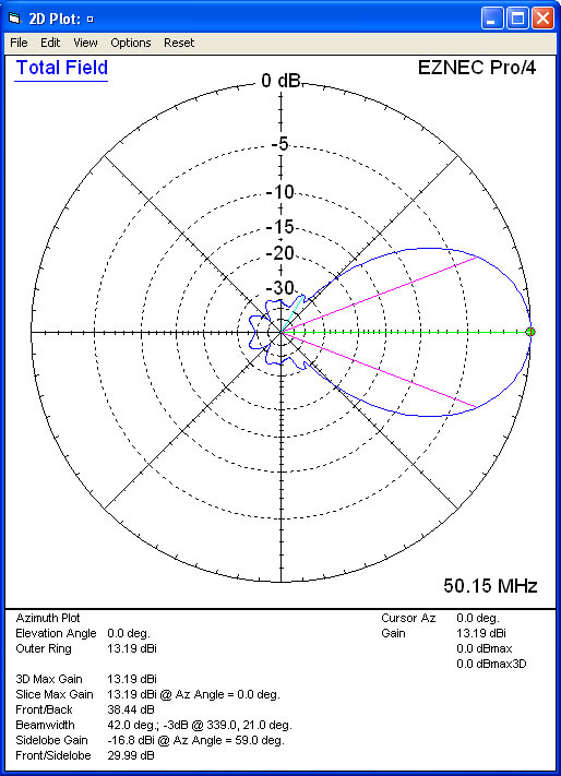
For detailed analysis of the radiation pattern I used an Icom 756proIII and also an Icom 7700 both with AGC OFF. The RX was fed via a stepped attenuator and the audio output taken to a laptop running PolarPlot by G4HFQ (Ref 4).
Again using the constant signal from GB3MCB I was quickly able to confirm that the azimuth performance of the 8LFA was remarkable with all side and rear facing lobes 30dB or more down on the main lobe as predicted by the EZNEC pro4 plot. This is in stark contrast to the M 6M7JHV which has a front to back of 25dB and some significant side lobes. EZNEC modelling indicates that the same is true in elevation where, at 20m above ground the 8LFA has good secondary and tertiary forward lobes at around 13 and 21 degrees but with much reduced rear facing lobes.
Operational Observations
I have been using the two antennas side by side for almost a month now and have had lots of fun in the 2010 Es season. From my quiet far west of England location I have been unable to detect any real advantage whilst working to EU and ME. Coincidentally this (90deg) is the direction of my only source of power line noise. However, when working to the North East for JA etc the 8LFA has consistently out performed the JHV. Not with bigger signals but with much reduced local noise and signals from southern EU. I think I owe my JT0YAB QSO to listening on the 8LFA.
On 16th June during a JT65A eme QSO with KL7/KB7Q I had the two antennas running into two receivers and two laptops during receive periods. On average Gene seemed to be a couple of dB stronger on the 8LFA peaking at -21dB s/n in 2.4kHz. Not bad for single yagi to single yagi eme. My noise source was of course off the back of the antennas at this time.
On 5th July I spent an hour or so on 50.0875 working into the mid-West States out to DN and DM Fields and ending with 50 or so QSOs in the log. There were a number of occasions where I simply could not hear a station on the JHV that I worked on the 8LFA. Not that the signals were any stronger on the 8LFA - just that EU and my local noise source were at least 6-10dB weaker!
Unfortunately Murphy has ensured that we have not had any static rain (or much rain at all for several weeks) so I am unable to comment of the effects (if any) of the insulated elements. I intend to test DC grounding of the coax to the boom AFTER the choke or Balun at some point.
To Build or to Buy
The G0KSC website has full construction details for a wide and ever growing range of LFA and other antennas. Justin also offers advice on where to obtain hardware and element to boom clamps can be purchased on-line. So, why not give it a try. Commercial realizations of the G0KSC designs are available from Vine Antennas in the UK (Ref 3), Force 12 in the USA (Ref 5) and an increasing number of manufacturers worldwide. It really is quite amazing how many top DX stations are already using Justin's designs.
Summary
Though initially sceptical, I have now become a convert to the G0KSC designs, primarily because of the ease with which real antenna can be constructed from a computer generated model with the knowledge that it will be easy to set up and will then perform as modelled! Operationally the 8LFA should really come into it's own at a noisy location (thankfully I didn't get to test that!) where the clean pattern will help reduce local noise. This will also be true for eme work with the LFA elevated due to the small rear facing elevation lobes.
What's Next
Well, I have a new M2 6M8GJ designed for Lance W7GJ and as used so successfully by him for eme from E51. The plan is to compare this against a later design of the G0KSC 6M8LFA. Then on to building the box of 4;-)
73 Peter G8BCG IO70RK
References:
2. www.uksmg.com/content/m2_6m7jhv.htm